Industry Software Application Center (ISAC)
This project was launched across faculties at the OTH Amberg in order to make key automation technology usable for medium-sized companies, in order to arm them for the new challenges of advancing digitisation.
The Smart Factory Demonstrator
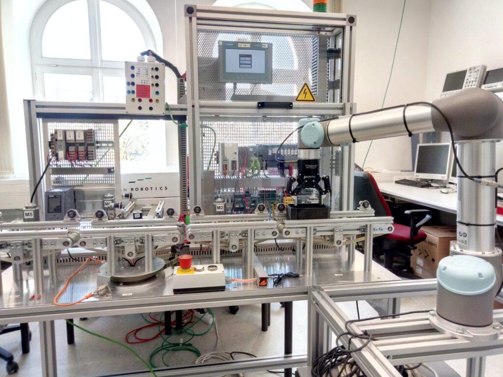
An Industry 4.0 demonstrator is being set up as part of ISAC sub-project 3. The aim of this demonstrator is to convey and “process” workpieces according to current I4.0 standards. The workpieces are located in a workpiece carrier that is equipped with a writable RFID chip. In the course of “production”, the demonstrator’s sensors read out individual data (e.g. form or colour) and store this information on the RFID chip of the workpiece. Depending upon the dynamically definable steps, the workpiece may then be handled differently. The workpieces can be sorted according to e.g. colour or form, or they can then be “processed” individually. Control can either take place via the individual PLCs with equal rights in the various modules, or optionally from a central, higher-level PLC. A visualisation of the individual data on screens or the connection to other systems is optional.
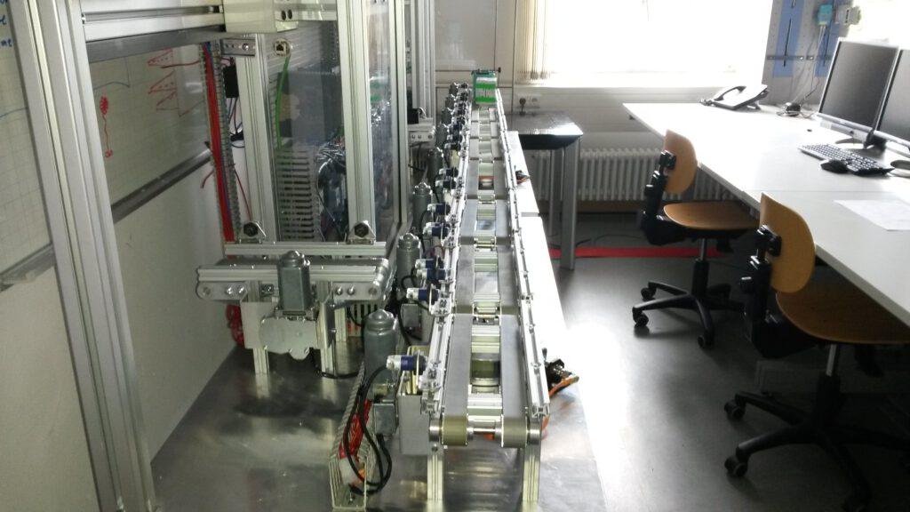
The special feature of this Industry 4.0 demonstrator is its modular design. Eight independent conveyor modules form the basis of the demonstrator. The modules recognize each other via Barcodes. Thanks to the modular design and mutual “neighbourhood recognition” of the individual modules, this system can be rearranged during operation without the individual “production steps” of the workpieces getting mixed up. The eight modules are organised into two groups. Modules 1–4 are transverse conveyors. They have no sensors, but a turntable that enables conveyance in three different directions. Modules 5–8 have sensors/actuators. Here the physical data of the workpieces can be read and “processing” can take place.
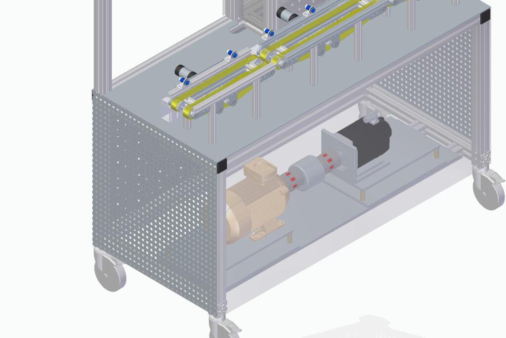
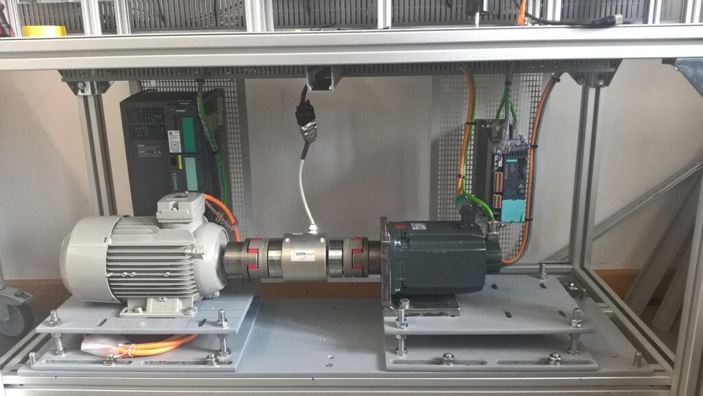
Furthermore, an engine test bench consisting of an ASM and a servomotor is installed in modules 6 and 8. They not only generate realistic malfunctions on the data line, but also dynamically transmit the current measured values (rotation rate, rotation direction, torque) to the PLC and display them on the HMI. These engines are currently under construction.
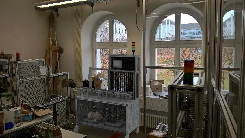
As with any industrial production system, the Industry 4.0 demonstration system should also offer solutions for maintenance, diagnosis and operation via a graphic user interface (HMI).In order to enable a high range of functions from the very beginning, and to simultaneously maintain an intuitively operable system, a virtual image of the system was created in the form of a 3D model. With the help of the virtual image, the operator can observe the system in live operation, view the current positions of components and their data and e.g. call up the current processing status. In the event of a malfunction, the exact position of the affected components can be displayed in the 3D model. This virtual representation of the system also offers limited control options. For safety reasons, no individual movements can be carried out in the system; however, the automatic mode can be started, stopped and paused, for example.
The low-cost community solution Unity was chosen as the engine for the 3D model. Unity is widely used in independent game development. This has the advantage that solutions or examples already exist for numerous tasks. And there are no licence fees for non-commercial use of the engine. As Unity supports the development for numerous target platforms, the developed HMI can not only be used on numerous PC systems, but also in a web browser or on mobile devices. In addition to a PC-based implementation, one for Android was also created so that the system can also be accessed via smartphone and tablet.